Lancia MUSA. Service Manual - part 1


  Index      Manuals     Lancia MUSA. Service Manual


Search            copyright infringement  


Content      ..       1      2      ..


Lancia MUSA. Service Manual - part 1


8

SAFETY

ST

AR

TING

AND DRIVING

W

A

RNING

LIGHTS AND

MESSAGES

IN AN

EMERGENCY

MAINTENANCE

AND CARE

TECHNICAL

SPECIFICA-

TIONS

INDEX

DASHBOARD

AND

CONTROLS

L0D0374m

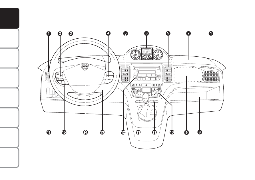
1. Side air vents - 2. Left stalk- 3. Left upper box  - 4. Right stalk - 5. Central air vents - 6. Instrument panel - 7. Right up-

per box  - 8. Oddment compartment Passenger airbag - 10. HVAC controls - 11. Control buttons 12 Sound system (for ver-

sions/markets, where provided) - 13. Ignition switch - 14. Driver airbag - 15. Cruise control (for versions/markets, where

provided). 

DASHBOARD

The presence and position of the controls, instruments and gauges may vary depending on the version. 
There are several solutions for the central upper and lower console according to the chosen customisations: see the following

figures.

fig. 1

-------------------------------------------------------------------------------------------------------------------------------------------------------------

9

SAFETY

ST

AR

TING

AND DRIVING

W

A

RNING

LIGHTS AND

MESSAGES

IN AN

EMERGENCY

MAINTENANCE

AND CARE

TECHNICAL

SPECIFICA-

TIONS

INDEX

DASHBOARD

AND

CONTROLS

Upper central console:

❒ with fixed oddment compartment

A-fig. 2 and extractable compo-

nent (DIN) B-fig. 2 for installing

the sound system;

❒ with sound system fig. 3.

❒ with Connect Nav+ fig. 4.

Lower central console:

❒ with manual climate control system

B-fig. 5;

❒ with two-zone automatic climate

control system C-fig. 6.

fig. 2

L0D0231m

fig. 3

L0D0232m

fig. 4

L0D0359m

fig. 5

L0D0234m

fig. 6

L0D0235m

-------------------------------------------------------------------------------------------------------------------------------------------------------------

10

SAFETY

ST

AR

TING

AND DRIVING

W

A

RNING

LIGHTS AND

MESSAGES

IN AN

EMERGENCY

MAINTENANCE

AND CARE

TECHNICAL

SPECIFICA-

TIONS

INDEX

DASHBOARD

AND

CONTROLS

L0D0372m

L0D0010m

fig. 7

fig. 8

INSTRUMENT PANEL

Modal fig. 7

A – Speedometer 

B – Fuel level gauge with reserve warning light

C – Engine coolant temperature gauge and hot

engine coolant warning light 

D – Rev counter

E – Multifunctional display 

c m Warning lights for Multijet versions only

Comfort fig. 8

A – Speedometer 

B – Fuel level gauge with reserve warning light

C – Engine coolant temperature gauge and hot

engine coolant warning light 

D – Rev counter

E – Reconfigurable multifunctional display 

c m Warning lights for Multijet versions only

-------------------------------------------------------------------------------------------------------------------------------------------------------------

11

SAFETY

ST

AR

TING

AND DRIVING

W

A

RNING

LIGHTS AND

MESSAGES

IN AN

EMERGENCY

MAINTENANCE

AND CARE

TECHNICAL

SPECIFICA-

TIONS

INDEX

DASHBOARD

AND

CONTROLS

SYMBOLS

Special coloured labels have been at-

tached near or actually on some of the

components of your car. These labels

bear symbols that remind you of the

precautions to be taken as regards

that particular component.

The plate summarising the symbols

used can be found under the bonnet

fig. 9.

THE LANCIA CODE
SYSTEM

This is an electrical engine locking

system which increases protection

from attempted theft of the car. It is

automatically activated when the ig-

nition key is extracted.

Each key contains an electronic de-

vice which modulates the signal emit-

ted during ignition by an antenna in-

corporated in the ignition device. This

signal is the ‘password’ which changes

at each ignition and which the control

unit uses to recognise the key and al-

low ignition. 

fig. 9

L0D0375m

-------------------------------------------------------------------------------------------------------------------------------------------------------------

12

SAFETY

ST

AR

TING

AND DRIVING

W

A

RNING

LIGHTS AND

MESSAGES

IN AN

EMERGENCY

MAINTENANCE

AND CARE

TECHNICAL

SPECIFICA-

TIONS

INDEX

DASHBOARD

AND

CONTROLS

Warning light 

coming on

when driving

❒ If the warning light 

Y

turns on,

this means that the system is run-

ning a self-test (for example for a

voltage drop). 

❒ If the fault persists, contact a Lan-

cia Dealership.

OPERATION

Each time the car is started turning

the ignition key to MAR, the Lancia

CODE system control unit sends a

recognition code to the engine control

unit to activate the functions. The

code is sent only if the Lancia CODE

system control unit has recognised the

code transmitted from the key. Each

time the ignition key is turned to

STOP, the Lancia CODE system de-

activates the functions of the engine

electronic control unit.

If the code has not been recognised

correctly, the warning light 

Y

turns

on on the display.

The electronic components
inside the key may be dam-
aged if the key is submitted
to sharp knocks.

In this case, turn the key to STOP

and then back to MAR; try with the

other keys provided if the problem

persists. Contact a Lancia Dealership

if you still cannot start the engine.

IMPORTANT Each key has its own

code which must be stored by the sys-

tem electronic control unit. Contact a

Fiat Dealership to have new keys (up

to eight) stored.

-------------------------------------------------------------------------------------------------------------------------------------------------------------

13

SAFETY

ST

AR

TING

AND DRIVING

W

A

RNING

LIGHTS AND

MESSAGES

IN AN

EMERGENCY

MAINTENANCE

AND CARE

TECHNICAL

SPECIFICA-

TIONS

INDEX

DASHBOARD

AND

CONTROLS

KEY KIT AND
DOOR LOCKING
SYSTEM

CODE CARD Fig. 10
(for versions/markets, where
provided)

The car is delivered the keys and a

CODE card which bears the following

information:
❒ the mechanical key code to be

given to the Lancia Dealership

when ordering duplicate keys.

IMPORTANT In order to ensure per-

fect efficiency of the electronic devices

contained inside the keys, they should

never be exposed to direct sunlight.

MAIN KEY WITH REMOTE
CONTROL fig. 11
The metal insert of the key retracts

into the grip.
The key operates:
❒ the ignition switch;

❒ the door lock on drive side;

❒ operation of the emergency front

and rear door lock release system

D-fig. 12 from the outside for use

the electric system is not working

(e.g. flat battery);

fig. 10

L0D0376m

All the keys and the CODE
card must be handed over
to the new owner when sell-
ing the car.

fig. 11b 

(for versions/markets,

where provided)

L0D0491m

❒ operation of the child lock E-fig.

12 on rear doors.

Press button B-fig. 11 to open the

metallic part A.

fig. 12

L0D0246m

fig. 11a

L0D0377m

-------------------------------------------------------------------------------------------------------------------------------------------------------------

14

SAFETY

ST

AR

TING

AND DRIVING

W

A

RNING

LIGHTS AND

MESSAGES

IN AN

EMERGENCY

MAINTENANCE

AND CARE

TECHNICAL

SPECIFICA-

TIONS

INDEX

DASHBOARD

AND

CONTROLS

By using the “Setup Menu” of the

multifunctional display (see the spe-

cific paragraph in the “Dashboard

and controls” chapter), the system

can be set so that only the driver’s

door is unlocked when button Ë is

pressed.

IMPORTANT Powerful radio trans-

missions not related to the car (e.g.

mobile phones, amateur radios, etc.)

may interfere with the frequency of

the remote control. Remote control

operation may be impaired.

Unlocking the doors and the
tailgate

Press button 

Á

briefly: this will release

the doors, the tailgate, the fuel flap;

the internal ceiling light will come on

and the direction indicators will blink

twice.

Unlocking the doors and the
tailgate

Press button Ë briefly: this will release

the doors, the tailgate, the fuel flap;

the internal ceiling light will come on

and the direction indicators will blink

twice.

The doors are automatically unlocked

when the fuel inertia switch trips.

To insert the metallic part back in

the grip: 
❒ hold button pressed 
❒ move the metallic part  A
❒ release button and then turn the

metal insert until it clicks.

Button

Ë

is used to open the doors,

tailgate and fuel flap (where pro-

vided).

Button

Á

is used to lock the doors,

tailgate and fuel flap (where pro-

vided).

Button

R is used for remote open-

ing the tailgate.

Only press button B with
the key away from your

body, specifically from your eyes
and from objects which could get
damaged (e.g. your clothes). Do not
leave the key unattended, because
someone, a child especially, may
accidentally press the button while
handling the key.

WARNING

-------------------------------------------------------------------------------------------------------------------------------------------------------------

15

SAFETY

ST

AR

TING

AND DRIVING

W

A

RNING

LIGHTS AND

MESSAGES

IN AN

EMERGENCY

MAINTENANCE

AND CARE

TECHNICAL

SPECIFICA-

TIONS

INDEX

DASHBOARD

AND

CONTROLS

Deterrent LED indications

When locking the doors, the deterrent

LED on the button  A-fig. 13 lights

up for about 3 seconds and than starts

flashing (deterrence function). Once

doors are locked, if one or more doors

or the tailgate are not closed correctly,

the led and direction indicators start

flashing quickly.

IMPORTANT Strong radio transmis-

sion outside the vehicle (e.g. mobile

phones, amateur radios, etc.) may in-

terfere with the frequency of the re-

mote control. Remote control opera-

tion may be impaired.

Door locking from the inside

With the doors closed, press button  

A-fig. 13 on the central dashboard to

lock or unlock the doors.

IMPORTANT If the door is not cor-

rectly closed or if a fault is present in

the system, the door locking device

from inside the car will not work.

The device will resume normal oper-

ation after removing the cause of the

fault.

Opening the tailgate with the
remote control

Hold button  

R pressed to unlock

(open) the tailgate. The opening of

the tailgate is signalled by the direc-

tion indicators flashing twice; when it

is closed there is one flash.

IMPORTANT Strong radio transmis-

sion outside the vehicle (e.g. mobile

phones, amateur radios, etc.) may in-

terfere with the frequency of the re-

mote control. Remote control opera-

tion may be impaired.

fig. 13

L0D0417m

Only the doors used to get
out of the car will be un-
locked if the door lock but-
ton inside the car is pressed

by mistake. The tailgate will remain
locked. Press the lock/unlock but-
tons to realign the system.

-------------------------------------------------------------------------------------------------------------------------------------------------------------

16

SAFETY

ST

AR

TING

AND DRIVING

W

A

RNING

LIGHTS AND

MESSAGES

IN AN

EMERGENCY

MAINTENANCE

AND CARE

TECHNICAL

SPECIFICA-

TIONS

INDEX

DASHBOARD

AND

CONTROLS

Request for additional remote
controls

The system may recognise up to 8 re-

mote controls. Should a new remote

control be necessary, contact a Lancia

Dealership, taking with you the

CODE card, a personal identity doc-

ument and the car’s ownership docu-

ments.

MECHANICAL KEY 
(SPARE) fig, 15

The metal insert of the key E-fig. 15

is fixed.

The key operates:
❒ the ignition switch;
❒ the door lock on drive side;
❒ operation of the door safety device

in case of electric system failure

(e.g. flat battery);

❒ operation of the child lock on rear

doors.

Replacing the remote control
battery Fig. 14

To replace the battery, proceed as fol-

lows:
❒ press button and open the metal

insert B;

❒ turn the screw to using a fine bit

screwdriver;

❒ take out the battery case and re-

place the battery respecting its

polarity;

❒ refit the battery case inside the

key and lock it by turning the

screw C.

fig. 14b 

(for versions/markets, where

provided)

L0D0492m

Used batteries are harmful
to the environment. They
should be disposed of as
specified by law in the spe-

cial containers provided, or take
them to the Lancia Dealership,
which will deal with their disposal.

fig. 14a

L0D0379m

-------------------------------------------------------------------------------------------------------------------------------------------------------------

17

SAFETY

ST

AR

TING

AND DRIVING

W

A

RNING

LIGHTS AND

MESSAGES

IN AN

EMERGENCY

MAINTENANCE

AND CARE

TECHNICAL

SPECIFICA-

TIONS

INDEX

DASHBOARD

AND

CONTROLS

Changing the remote control
cover fig. 16
(for versions/markets, where provided)

Proceed as shown in the figure to re-

place the remove control cover.

fig. 15

L0D0380m

fig. 16

L0D0380m

Only press button B with
the key away from your

body, specifically from your eyes
and from objects which could get
damaged (e.g. your clothes). Do not
leave the key unattended, because
someone, a child especially, may
accidentally press the button while
handling the key.

WARNING

-------------------------------------------------------------------------------------------------------------------------------------------------------------

18

SAFETY

ST

AR

TING

AND DRIVING

W

A

RNING

LIGHTS AND

MESSAGES

IN AN

EMERGENCY

MAINTENANCE

AND CARE

TECHNICAL

SPECIFICA-

TIONS

INDEX

DASHBOARD

AND

CONTROLS

Type of key

Spare 
mechanical
key

Main key with 
remote control

Direction indicators 
flash (for key 
with remote 
control only)

Deterrence led

Press button Ë to open the fuel flap.

The main functions that can be activated with the keys (with or without remote control) are the following:

Locking the doors 
from the outside

Turn key 
clockwise
(driver’s side)

Turn key 
clockwise
(driver’s side)

Press briefly 
button Á

blinks once 

Steady for approximately 
3 seconds and then 
deterrent blinking 

Unlocking the
tailgate

Hold pressed button 

R

(for longer than two seconds)

2 blinks

Deterrence led

Unlocking the doors

Turn key 
anticlockwise
(driver’s side)

Turn key 
anticlockwise
(driver’s side)

Press briefly 
button Ë

2 blinks

Turning off 

-------------------------------------------------------------------------------------------------------------------------------------------------------------

19

SAFETY

ST

AR

TING

AND DRIVING

W

A

RNING

LIGHTS AND

MESSAGES

IN AN

EMERGENCY

MAINTENANCE

AND CARE

TECHNICAL

SPECIFICA-

TIONS

INDEX

DASHBOARD

AND

CONTROLS

CHILD LOCK fig. 17

To prevent opening the rear doors

from the inside.

This device can be engaged only with

rear doors open.

position - device on (door

locked);

position - device off (door can be

opened from the passenger’s com-

partment).

The device A stays on even if the

doors are unlocked by the centralised

system.

IMPORTANT Always use this device

when transporting children.

IMPORTANT After engaging the

child lock on both rear doors, check

for proper engagement by trying to

open a rear door with the internal

handle.

To reopen the doors:

insert the key in the lock on dri-

ver’s side and turn it anticlockwise 

open the driver’s door 

operate the door levers from the

inside of the vehicle for the re-

maining doors.

fig. 17

L0D0101m

Operation of the child lock
A-fig. 19 is only guaran-

teed if the lock is turned and snaps
into horizontal position 1.

WARNING

Release of the child lock
A-fig. 17 is only guaran-

teed if the lock is turned and snaps
into the vertical position 2.

WARNING

EMERGENCY DOOR
UNLOCKING DEVICE   fig. 18

The doors are provided with a device

for locking all the door using the lock

in case of a power fault.

Proceed as follows to lock the doors: 

insert the ignition key in lock B

turn the device to position  and

close the door. 

fig. 18

L0D0247

Do not operate the child
lock and the door handle

at the same time.

WARNING

-------------------------------------------------------------------------------------------------------------------------------------------------------------

20

SAFETY

ST

AR

TING

AND DRIVING

W

A

RNING

LIGHTS AND

MESSAGES

IN AN

EMERGENCY

MAINTENANCE

AND CARE

TECHNICAL

SPECIFICA-

TIONS

INDEX

DASHBOARD

AND

CONTROLS

IGNITION SWITCH

The key can be turned to 3 different

positions:
❒ STOP: engine off, key extractable,

steering locked. Some electric de-

vices (e.g. sound system, central

door locking system, etc.) may

work.

❒ MAR: driving position. All electric

devices may work.

❒ AVV: engine starting (unstable po-

sition).

The ignition switch is fitted with a

safety system that, in the event the en-

gine is not started, turns back the ig-

nition key to STOP before repeating

the starting operation.

Under no circumstances
should aftermarket opera-

tions involving steering system or
steering column modifications (e.g.:
installation of alarm) be carried
out that could badly affect perfor-
mance and safety. This also causes
the warranty to become null and
void and results in vehicle non-
compliance with type-approval re-
quirements.

WARNING

fig. 19

L0D0021m

If the ignition device is
tampered with (e.g.: at-

tempted theft), have it checked over
by a Lancia Dealership as soon as
possible.

WARNING

Always remove the key
when you leave your car to

prevent someone from accidentally
operating the controls. Remember
to apply the handbrake. Engage
first gear if the car is parked up-
hill or reverse if the car is parked
downhill. Never leave children un-
attended in the car.

WARNING

STEERING LOCK

Engagement

When the key is in position STOP, re-

move the key and turn the steering

wheel until it is locked.

Switching off

Rock the steering wheel slightly as you

turn the ignition key to MAR.

Never extract the key while
the vehicle is moving. The

steering wheel would be locked as
soon as the steering wheel is turned.
This also applies to when the car is
towed.

WARNING

-------------------------------------------------------------------------------------------------------------------------------------------------------------

21

SAFETY

ST

AR

TING

AND DRIVING

W

A

RNING

LIGHTS AND

MESSAGES

IN AN

EMERGENCY

MAINTENANCE

AND CARE

TECHNICAL

SPECIFICA-

TIONS

INDEX

DASHBOARD

AND

CONTROLS

INSTRUMENTS

SPEEDOMETER Fig. 20

This indicates the vehicle speed.

REV COUNTER Fig. 21

This indicates the engine revolution

per minute. 

IMPORTANT The electronic injection

control system gradually shuts off the

flow of fuel when the engine is ‘over-

revving’ resulting in a gradual loss of

engine power.

When the engine is idling, the rev

counter may indicate a gradual or

sudden increase of the speed.

This is normal and does not indicate

a fault. It may be caused, for exam-

ple, by the operation of the climate

control system or fan. In these case, a

slow change in engine speed is used to

protect the battery charge.

The reserve warning light turns on

to indicate that approximately 

6 litres of fuel are left in the tank.

Do not travel with the tank nearly

empty: lack of fuel supply could dam-

age the catalyser.

FUEL LEVEL GAUGE Fig. 22

The instrument shows the litres of fuel

contained in the tank  (see the “Refu-

elling” paragraph for a description).

fig. 20

L0D0241m

fig. 22

L0D0023m

fig. 21

L0D0242m

fig. 23

L0D0024m

-------------------------------------------------------------------------------------------------------------------------------------------------------------

22

SAFETY

ST

AR

TING

AND DRIVING

W

A

RNING

LIGHTS AND

MESSAGES

IN AN

EMERGENCY

MAINTENANCE

AND CARE

TECHNICAL

SPECIFICA-

TIONS

INDEX

DASHBOARD

AND

CONTROLS

MULTIFUNCTIONAL
DISPLAY 
(on two-line modal
panel)

The car can be equipped with the mul-

tifunction display for showing useful in-

formation necessary when driving ac-

cording to settings.

ENGINE
COOLANT TEMPERATURE 
GAUGE fig. 23

Warning light indicates overheating

of the engine coolant. In this case, stop

the engine and contact a Lancia Deal-

ership. This shows the temperature of

the engine coolant fluid and starts

working when the fluid temperature ex-

ceeds approx. 50°C. In normal condi-

tions, the needle may point to different

positions according to use and the en-

gine cooling system management.

IMPORTANT The needle will point to

the lowest value of the scale (low tem-

perature) and warning light will

light up  to indicate a fault in the sys-

tem. Go to a Lancia Dealership to

have the system checked.

If the needle reaches the red
area, stop the engine imme-
diately and contact a Lan-
cia Dealership.

fig. 24

L0D0497m

“STANDARD” SCREEN  fig. 24

The standard screen shows the fol-

lowing information:

Odometer (kilometres or miles

travelled)

Clock (always displayed, even

with key extracted and front doors

closed)

Headlight adjustment (only with

dipped beam headlights on)

Gear shift suggestion.

NOTE When opening one of the front

doors, the display will turn on and

show for a few seconds the clock and

the kilometres or miles covered.

-------------------------------------------------------------------------------------------------------------------------------------------------------------

23

SAFETY

ST

AR

TING

AND DRIVING

W

A

RNING

LIGHTS AND

MESSAGES

IN AN

EMERGENCY

MAINTENANCE

AND CARE

TECHNICAL

SPECIFICA-

TIONS

INDEX

DASHBOARD

AND

CONTROLS

CONTROL BUTTONS fig. 25

+

To scroll the menu and the next

options or to increase the dis-

played value.

MODE

Press briefly to access the

menu and/or go to next

screen or to confirm the re-

quired menu option.

Hold pressed to go back to

the standard screen.

To scroll the menu and the previ-

ous options or to decrease the dis-

played value.

NOTE Buttons 

+

and

activate dif-

ferent functions according to the fol-

lowing situations.

❒ Hold button MODE pressed for

longer than two seconds to con-

firm the change made to the time.

Setting the buzzer volume 

To set the desired volume, proceed as

follows:
❒ repeatedly press MODE to display

bUZZ”;

❒ press to increase the volume;
❒ press – to decrease the volume;
❒ Hold button MODE pressed for

longer than two seconds to con-

firm the change made.

Setting the speed limit 

A speed limit can be set and the sys-

tem will inform the drive when the

limit is exceeded by means of an in-

dication on the display and the

buzzer. Proceed as follows to set:

This function is  “OFF” when the car

is delivered.

SET-UP MENU

The “Set-up Menu” is used for the

following adjustments and/or settings:
❒ SETTING THE CLOCK
❒ SETTING THE BUZZER VOL-

UME

❒ SETTING THE SPEED LIMIT
❒ SETTING THE UNIT OF MEA-

SUREMENT.

Setting the clock 

The clock is set to 24 hours when the

car is delivered.

Proceed as follows to set the required

time:
❒ repeatedly press MODE to display

“Hour”;

❒ press to increase one minute;
❒ press – to decrease one minute;
Hold buttons  or – pressed for a few

seconds to run the clock forwards or

backwards rapidly until the buttons

are released.

fig. 25

L0D0384m

-------------------------------------------------------------------------------------------------------------------------------------------------------------


Content      ..       1      2     ..